VCO clone, originally made by HAGIWO (link in japanese)
RP2040 chord VCO clone in SMD.
5-polyphonic Chord VCO module. There are 8 types of tones. With a built-in quantizer and automatic harmonics function, if you input a suitable CV, it will play a nice chord progression.
Module Specs
Eurorack standard, 3U 4HP
| rail | Power |
|---|---|
| +12V | 47mA |
| -12V | 8mA |
| 5V | 0mA |
Functionalities
Tune pot
Set the root frequency.
Chord pot
Select from 6 types of chord tables for automatic harmonics.
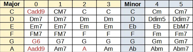
Inversion pot
Choose from 8 types of CHORD inversion. For example, “C,E,G” → “E,G,C” → “G,C,E”
Can be controlled via the INV CV input (0-5V).
Mode toggle switch
You’ll notice numbers along the central 3 position toggle switch. The table below explains each position’s function.
| Position | Function |
|---|---|
| 1 | arpeggio |
| 2 | chord with Bass |
| 3 | chord mode |
- “ARPEGGIO mode” is monophonic. Only single notes. The notes that are played are the constituent notes of CHORD, and are selected with INVERSION CV.
- “CHORD mode” only plays the constituent notes of a chord. Example: “C,E,G”.
- “CHORD with BASS mode” plays the constituent notes of a chord as well as the root note one octave lower.
Wave button
Press this button to change the wavetable. SAW, SIN, SQU, TRI, Dual SAW, FM1, FM2, FM3, 8 sounds in total.
V/oct input
input range 0-5V. This input is quantized.
Output
Output range 10Vp-p. No DAC is used on the audio output, just PWM via low pass filters. There will be harmonics in the output.
If you want to improve the output, you could replace the current output stage with a DAC.
Schematics

BoM
You can donwload the bom in excel format here
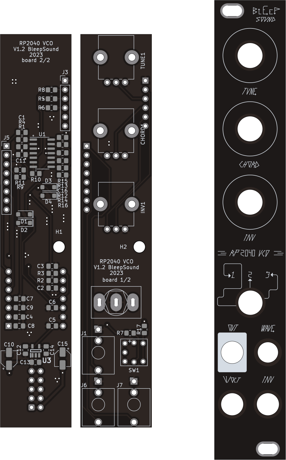
Build Informations
Full CMS build
![]() When building this module, do it in this order (from smallest component to tallest):
When building this module, do it in this order (from smallest component to tallest):
- Start by soldering all the CMS components in the order you want on both sides of the PCB.
- Then do all the through hole components
- To solder the headers, place them and place both PCBs in their final position before fully soldering the pin headers/sockets.
For the next parts, always place them without soldering them on:
- jacks, pots and switches that go throught the front panel
Once placed, put the front panel in place, then fasten all components to it. Once this is done, you can solder all the remaining components.
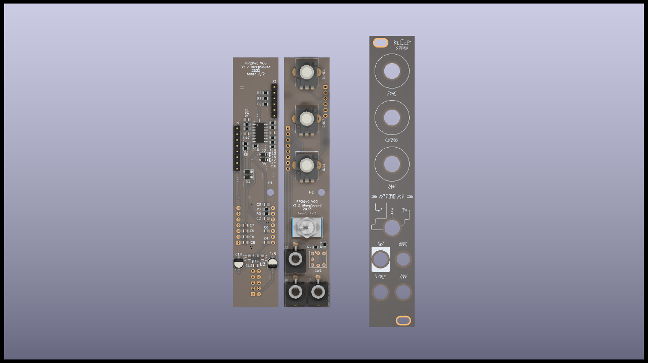
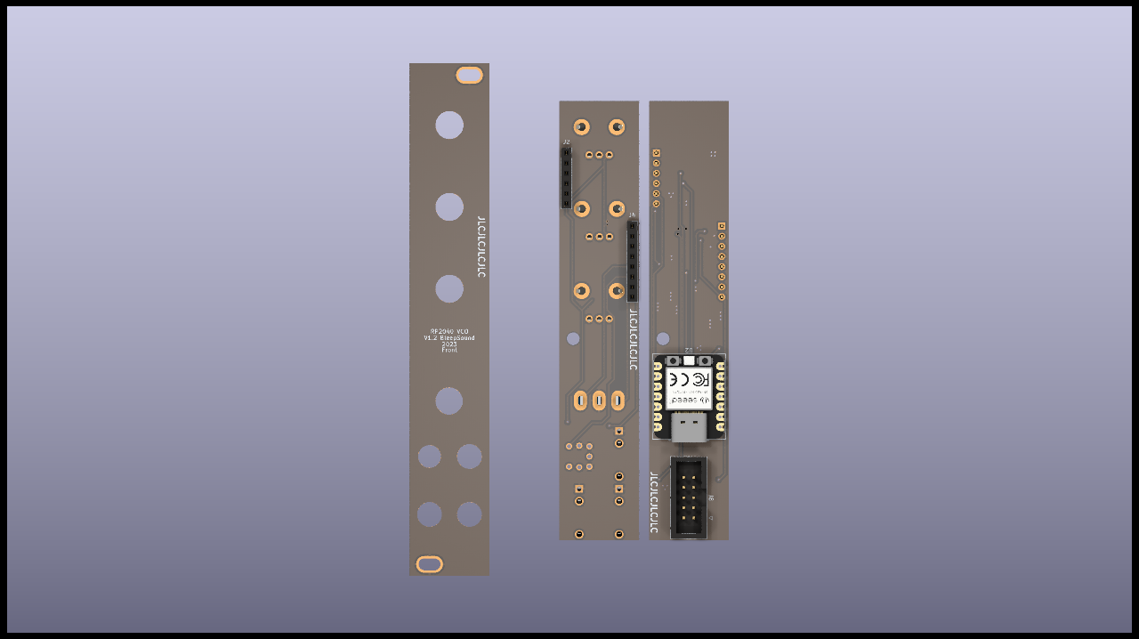
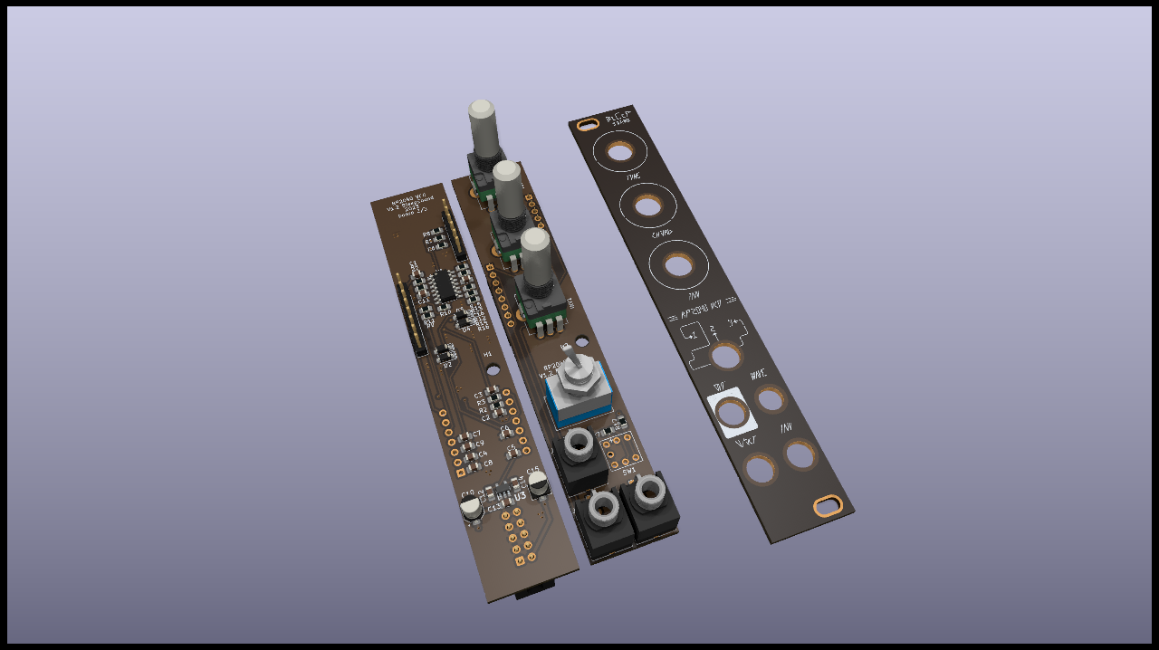
Images
Software
You can download the software for that module here or in the download link below.
The microcontroler model is: Seeed XIAO RP2040
To flash it, use a usb-c cable to connect the RP2040 to your computer and use the arduino IDE (or your preferred IDE) to flash the microcontroler.
If you need any help, you can find a tutorial on how to flash a software via arduino onto the RP2040 here.
Version
V1.1
- you HAVE TO rotate SW1 180° for the built in LED to work.
- Issues on front panel (wrong label and missing info)
V1.2
- Fix issues on SW1
- Update front panel look to include all informations
V1.4
- Add R18 (10k) resistor to CV Inv input
- Update BoM with extra details and informations
V1.5
- Reverse all pots because they were backwards.
Download
Follow this link if you want to dowload the latest version of gerber files, schematic, kicad files…
![]()
This work is licensed under a Creative Commons Attribution-ShareAlike 4.0 International License.

Leave a comment