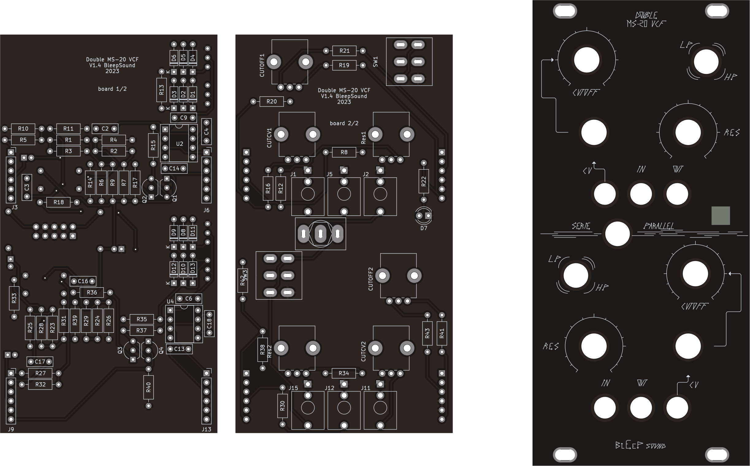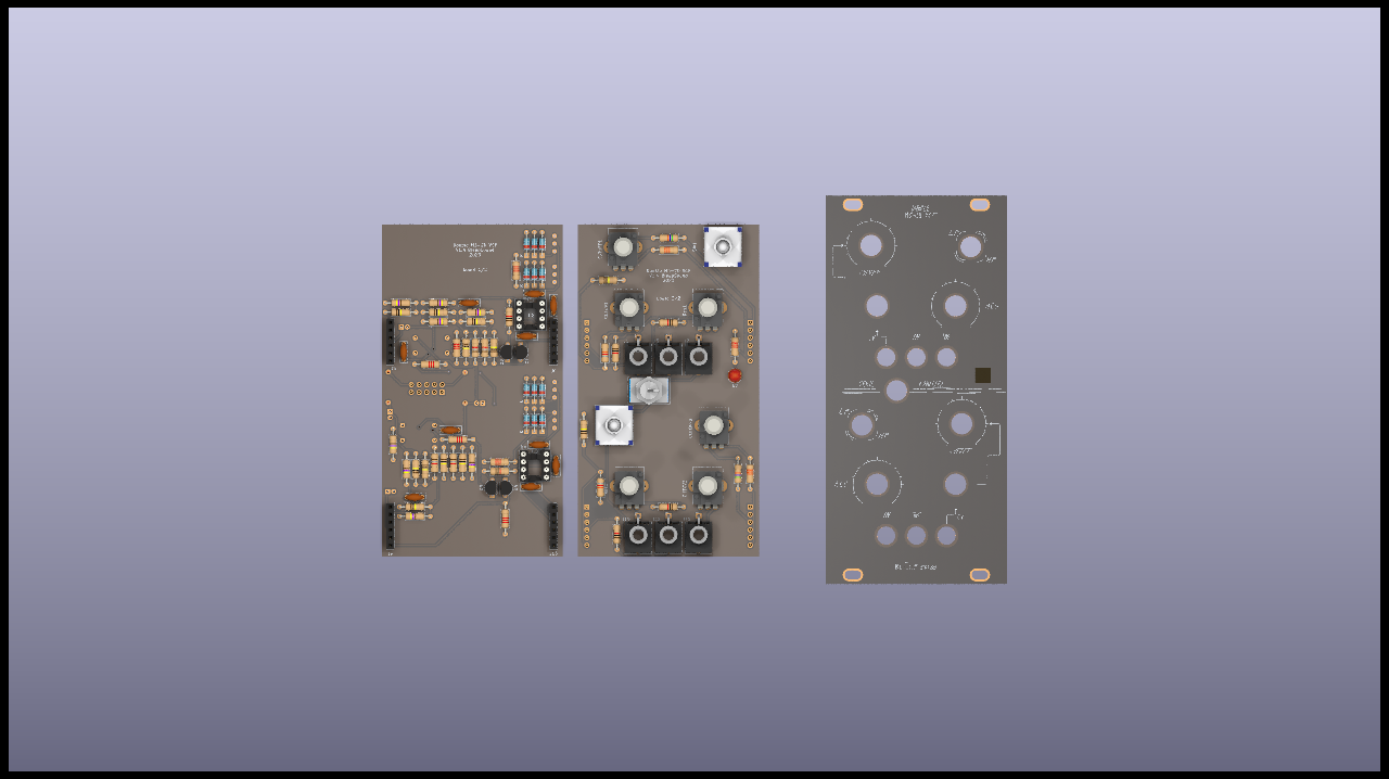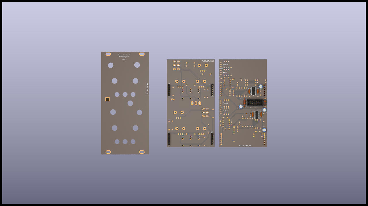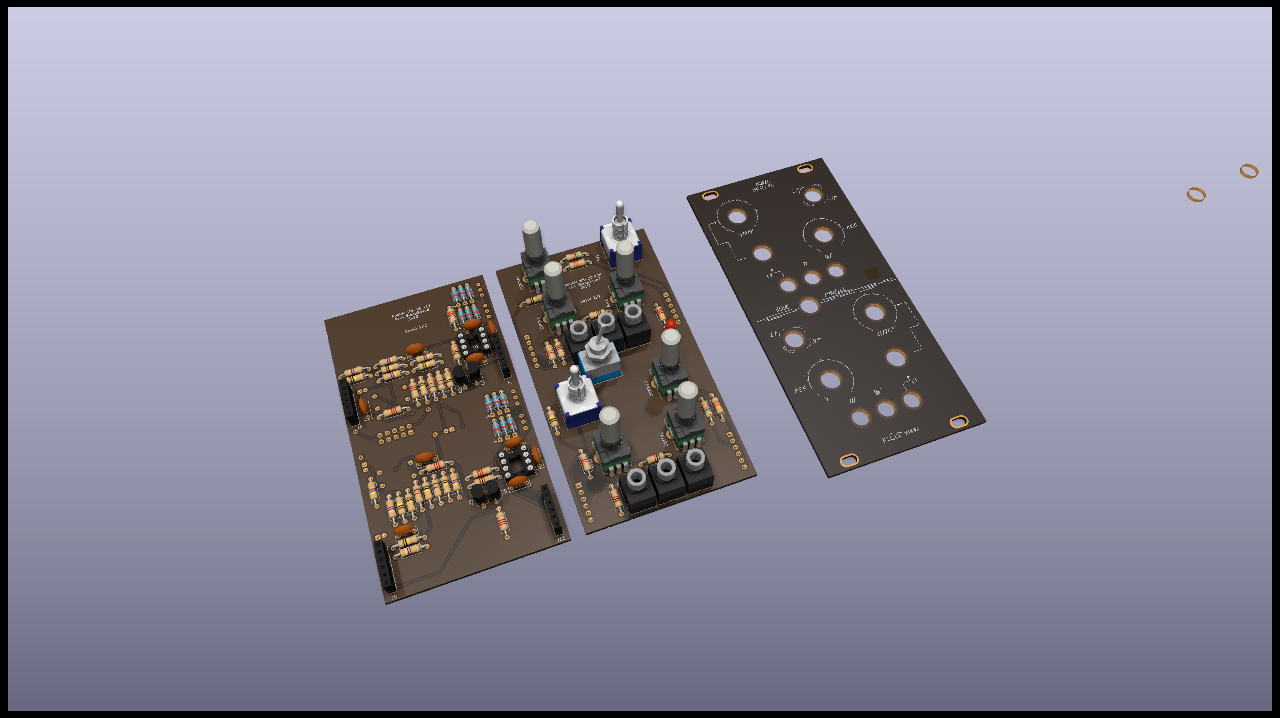
MS20-VCF clone based on BartonSynth version.
Size: 12HP
Two independant Sallen-key (MS-20 VCF style) filters.
Cutoff + Resonance, with a switch to chose low pass or high pass mode.
CV control on the filter cutoff, both CV inputs are normaled to one another, so you can control the cutoff of both filters with just one CV signal.
The output of the first filter (top) is normaled to the input of the second one, effectivaly putting both filters in series. If you plug a jack into the out of filter 1 (top), you will sever that link. Same if you put a jack in the input of filter 2 (bottom).
Self oscilation if resonance pushed to maximum, can be adjusted with 2 trimmers :
- 1 trimmer for the sine wave amplitude (resVol)
- 1 trimmer for the level at which the knob for resonance starts the self oscillation (resLvl)
Module Specs
Eurorack standard, 3U 12HP
| rail | Power |
|---|---|
| +12V | 42mA |
| -12V | 40mA |
| 5V | 0mA |
Schematics
You’ll find only the first filter below, the second filter is exactly the same.
BoM
You can donwload the bom in excel format here.
Build Informations
Uses an SMD LM13700 because the DIP ones are not produced anymore, hence more expensive.
Regular build, I use ceramic capacitors but you can use film/polyester.
![]() When building modules, work your way up from small to big (any SMD stuff first, then through hole stuff following that list):
When building modules, work your way up from small to big (any SMD stuff first, then through hole stuff following that list):
- diodes
- resistors
- DIP chips
- capacitors (film/ceramic)
- Transistors
- Electrolytic capacitors
To solder the headers, place them and place both PCBs in their final position before fully soldering the pin headers/sockets.
For the next parts, always place them without soldering them on:
- jacks, pots and switches that go throught the front panel
For SynthShed kits: Use the spline shaft pots as the cutoff pot (central one), and use the round shaft pots for res and CV attenuation
Once placed, put the front panel in place, then fasten all components to it. Once this is done, you can solder everything.
Images


Version
V1.4
- Functionnal, will work as is
- previous layout which I think wasn’t the best
V2.0
- Update front panel and pots positions
- Change normalization btw inputs to put both filter in series
- CV normalized to one another
Download
Follow this link if you want to dowload the latest version of gerber files, schematic, kicad files…
This work is licensed under a Creative Commons Attribution-ShareAlike 4.0 International License.


Leave a comment